Build Instructions (Version 3)
Before you start
- Skill level: beginner-friendly if you can 3D print + use a screwdriver.
- Time: first build usually takes a weekend.
- Goal: assemble + run the first motion test safely.
Rule #1: don’t force-fit parts. If it doesn’t fit, trim/sand gently.
1) Parts you’ll need (BOM)
Grab these parts before you start the build. Equivalent alternatives are fine as long as the specs match.
Bill of Materials
| Part | Qty | Buy link |
|---|---|---|
| ST3215-7.4v | x11 | |
| Waveshare Servo Driver with ESP32 (Wi-Fi) | x2 | |
| Newline 4K Webcam for PC with 2 Microphone, 1080P@60FPS, PDAF Autofocus in 1 Second, 12 Megapixels, Clear Stereo Sound, Auto Light Correction, USB Web Camera | x1 | |
| 7.5v 3000mah power supply | x1 | |
| 5.5 × 2.1mm DC power connector adapters (male + female screw terminals) | x1 pack | |
| M3 countersunk machine screws (assortment) | x1 kit | |
| Deep Groove Ball Bearings 3×8×3mm | x1 pack | |
| MMOBIEL 20 AWG electrical wire (parallel), 5m | x1 |
Tip: buy the parts first, then do servo centering before assembly.
If you’re missing one part, don’t panic — Nova forgives you. Mostly.
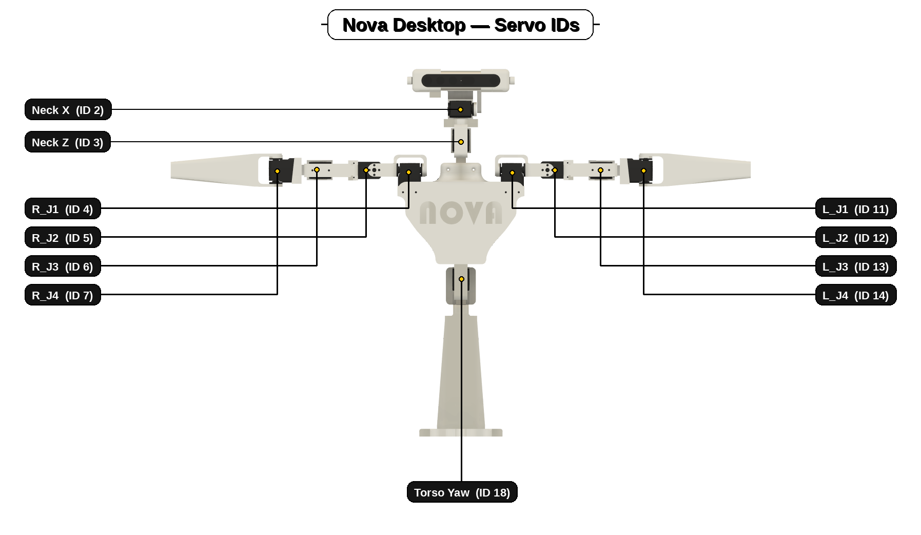
2) Setup — Set Servo ID's and center your servos first (do this BEFORE printing/assembly)
This step is mandatory. If you install servos without setting ID's and centering them first, you’ll end up with joints that hit hard stops, bind, or move off-angle (or worse: don’t respond to commands) — and it’s painful to fix later.
Do this first
- Set servo IDs. Make sure every servo has the correct ID for its joint (see the map above).
- Center every servo. Set each servo to its neutral/middle position before attaching horns and brackets.
- Only then assemble. Building around centered servos prevents binding and makes the “neutral pose” line up cleanly.
If a horn can’t be perfectly straight because of spline steps: choose the closest, then correct with a tiny software offset later.
3) Build Order (Recommended Sequence)
Print order matters. This sequence avoids rework and makes wiring + assembly much easier.
Recommended sequence
- Print the base first. Stable foundation — everything mounts cleanly once the base is solid.
- Print the torso next. The torso is the main hub — electronics and modules plug into it.
- Mount the servo drivers to the chest rear door (off the torso).
Arm driver at the top, torso+neck driver at the bottom. - Join torso housings + attach the rear door (don’t close it yet). Keep access open for wiring and plugs.
- Print arms + neck (any order). They’re modular and slot into the torso once ready.
Core idea: mount electronics early, keep access open until all servos are connected, then close up.
4) Arm Build
Build both arms the same way. Clean routing = smooth life.
Steps
- Print the arm parts. Clean supports and test-fit before committing to screws.
- Install centered servos, building outward (shoulder → forearm).
Build one joint at a time and keep the arm straight at neutral. - Route servo cables as you assemble. Leave slack at joints and avoid pinch points.
- Slot arms into the torso, screw in, then plug into the arm driver. Do this while the rear door is still open.
Tip: if anything binds, stop and check horn alignment — don’t “force” the joint past resistance.
5) Neck Build
The neck is modular — build it as a clean sub-assembly, then slot it into the torso.
Steps
- Print the neck parts. Clean supports and test-fit first.
- Install centered servos + assemble the neck mechanism. Centered servos = head sits straight at neutral.
- Route cables (leave slack for full motion). Make sure wires can’t snag when turning/nodding.
- Slot neck into torso, screw in, then plug into torso+neck driver. Do this before closing the rear door.
Tip: manually sweep yaw/pitch by hand before power-on — you’re checking for snags and pinch points.
6) Head + Camera Fitment (USB camera + clips) — fiddly bit
The head can be fiddly. Take it slow and don’t force it — tiny alignment tweaks make a big difference.
Install the camera (Version 3)
This step mounts the camera into the head pivot arms so it can pitch smoothly without binding. Getting the alignment right here massively improves face tracking stability.
- Make sure the pitch servo is centred.
Set the pitch servo to its neutral position before fitting the camera. - Place the camera between the mount arms.
Keep it square so the pivot feels smooth. - Start the bolts with washers (2 per side).
Bolt + two washers per side, lightly tightened. - Fully tighten + hand test the pivot.
Snug, don’t over-torque. It should pivot smoothly without wobble.
Tight pivot: re-seat washers and center the camera. Loose pivot: confirm two washers per side and snug bolts.
7) Install the servo driver boards
- Mount both ESP32 servo driver boards to the body’s rear door.
- Plug the neck and torso servos into one board.
- Plug the arm servos into the other board.
- Remember which board is which.
When you upload the scripts later, the arm script must go to the arm board and the torso/neck script must go to the torso/neck board — otherwise Nova won’t move correctly.