Build Instructions (Version 1)
Before you start
- Skill level: beginner-friendly if you can 3D print + use a screwdriver.
- Time: first build usually takes a weekend.
- Goal: assemble + run the first motion test safely.
Rule #1: don’t force-fit parts. If it doesn’t fit, trim/sand gently.
1) Parts you’ll need (BOM)
Grab these parts before you start the build. Equivalent alternatives are fine as long as the specs match.
| Part | Qty | Buy link |
|---|---|---|
| ST3215 30kg serial bus servos | x11 | |
| Intel RealSense D455 | x1 | |
| JIZZU 12V 10A Power Supply Adapter (120W) | x1 | |
| 5.5 × 2.1mm DC power connector adapters (male + female screw terminals) | x1 pack | |
| M3 countersunk machine screws (assortment) | x1 kit | |
| Deep Groove Ball Bearings 3×8×3mm | x1 pack | |
| MMOBIEL 20 AWG electrical wire (parallel), 5m | x1 |
Tip: buy the parts first, then do servo centering before assembly.
If you’re missing one part, don’t panic — Nova forgives you. Mostly.
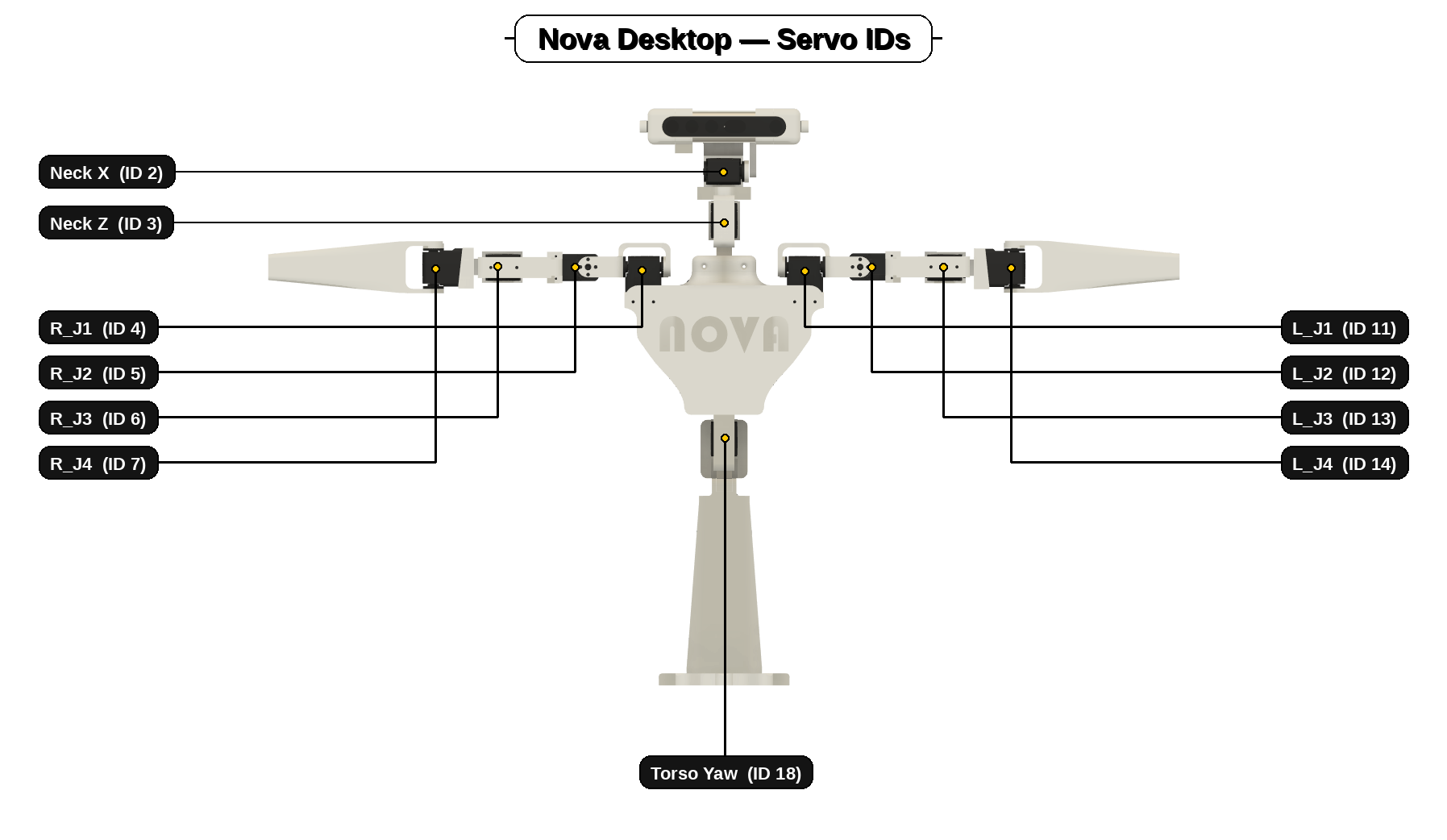
2) Setup — Set Servo ID's and center your servos first (do this BEFORE printing/assembly)
This step is mandatory. If you install servos without setting ID's and centering them first, you’ll end up with joints that hit hard stops, bind, or move off-angle (or worse: don’t respond to commands) — and it’s painful to fix later.
If a horn can’t be perfectly straight because of spline steps: choose the closest, then correct with a tiny software offset later.
3) Servo driver setup (ESP32) — upload code + Wi-Fi details
Do this early. Once your ESP32 boards are configured and online, the rest of the build is much smoother.
-
Open the ESP32 code in the Arduino IDE
Use the Arduino code editor to open the arm driver code and the torso+neck driver code. -
Install the SCServo library (FT&WS) in Arduino IDE
Go to Sketch → Include Library → Manage Libraries…
Search for SCServo and install “SCServo by FT&WS”.
Important: don’t add the library to the sketch manually — once installed via Library Manager, Arduino will include it automatically. -
Set your Wi-Fi name + password in the code
Replace the Wi-Fi SSID (network name) and Wi-Fi password in the ESP32 sketches with your own. -
Set your computer IP address (UDP target)
You’ll also need to add your laptop/PC IP address into the ESP32 code. On Windows: open Command Prompt and run ipconfig, then copy your IPv4 Address into the sketch. -
Upload the sketches to the ESP32 boards
Flash the code to each board (arm board + torso/neck board). -
Confirm Wi-Fi connection (status LED)
When the servo driver successfully connects to your router, the little white dot/LED will flash on and off.
Tip: keep the rear door open while doing this so you can access the boards easily.
4) Build Order (Recommended Sequence)
Print order matters. This sequence avoids rework and makes wiring + assembly much easier.
-
Print the base first
Stable foundation. Builds from the ground up and makes construction a breeze. -
Print the torso next
The torso is the main hub — everything plugs into it. -
Mount the servo drivers to the chest rear door (off the torso)
Recommended: arm driver at the top, torso+neck driver at the bottom. -
Join torso housings + attach the rear door (don’t close it yet)
Keep it open — you still need to connect the arm, torso and neck servos later. -
Print arms + neck (any order)
Arms and neck are modular — they slot into the torso easily and then screw in.
Core idea: mount electronics early, keep access open until all servos are connected, then close up.
5) Arm Build
Build both arms the same way. Clean routing = smooth life.
-
Print the arm parts
Print all arm segments. Clean supports and test-fit before you commit to screws. -
Install centered servos, building outward (shoulder → forearm)
Start at the first shoulder joint and build one joint at a time, keeping the arm laid out straight as you go. -
Route servo cables as you assemble
Leave slack at joints and make sure nothing can snag or pinch. -
Slot arms into the torso, screw in, then plug into the arm driver
With the rear door still open, connecting the arm servo leads is easy and tidy.
6) Neck Build
The neck is modular — build it as a clean sub-assembly, then slot it into the torso.
-
Print the neck parts
Print neck brackets. Clean supports and test-fit. -
Install centered servos + assemble the neck mechanism
Because servos are already centered, the head sits straight at neutral. -
Route cables (leave slack for full motion)
Make sure wires can’t pinch or snag when the neck turns or nods. -
Slot neck into torso, screw in, then plug into torso+neck driver
Do this before closing the rear door so you still have easy explainable access.
7) Head Fitment (RealSense + clips) — fiddly bit
The head can be fiddly. Take it slow and don’t force it — tiny alignment tweaks make a big difference.
-
Print the RealSense brackets/clips + servo linkages (and press in bearings)
Clean supports and test-fit the mating surfaces. Install the bearings into the camera mount. -
Assemble the bracket stack + mount the RealSense
Attach the right camera bracket first, then slide on: USB clip → linkage clip → left bracket. -
Route the camera USB safely
Route USB with slack for neck motion. No sharp bends, no pinch points. -
Fit the pitch linkage (horn backwards + washers + bearings)
Install horn pointing backwards. Use washers and don’t forget bearings. -
Test movement gently by hand
Test motion by hand and confirm the USB cable doesn’t bind.
If it feels tight: stop, loosen, re-seat, and re-route the USB. Forcing it always loses.
8) Next: Software installation
Once you’ve completed the steps in this build guide, move onto the software installation guide.